
Analyzing Electric Motor Designs with COMSOL Multiphysics®
The automotive industry is shifting its focus toward electric vehicles (EV), with a long-term objective of developing sustainable and environmentally friendly technologies for the future. In the last few decades, electric motors have found increasing use in automobiles due to increasing automation for greater passenger comfort. Motors are used in various systems of an automobile, such as the windshield wiper, coolant pump, power windows, as well as for traction in EVs.
In particular, permanent magnet motors (PMMs) are used for these applications, since they offer a wide range of advantages. They have a higher power density and torque-to-weight ratio compared to brushed DC or induction motors. They are more durable, as they do not make use of brushes. There is a pre-excitation by permanent magnets, which results in a higher efficiency. Lastly, they offer an unprecedented fast response, as they are electronically controlled. That is why acceleration rates as high as 0–60 mph in less than 2 seconds can be achieved for a passenger car.
In this article, we discuss a model of a PMM with 12 slots and 10 poles, analyzed using the COMSOL Multiphysics® simulation software, to explore different design and performance aspects of the machine. The machine model has an 80 mm axial length and 35 mm outer diameter. The model featured here can be used to study motors or generators by modifying the conditions for the inputs.
Model Setup
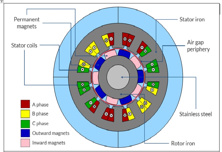
The schematic of the PMM shows all of the essential elements of the machine. From the modeling and simulation perspective, there are four main constituents: the stator iron, rotor iron, rotor permanent magnets, and the stator coils. The stator excitation usually consists of 3 phases: A, B, and C. The excitation pattern shown in the schematic is just one of the ways in which a 12-slot, 10-pole machine can be excited. The arrow head notation has been used to depict the direction of current in the stator coils. The arrow head (dot) implies current flowing out of the paper, while the arrow tail (cross) implies current flow into the plane of the paper.
Stator Excitation
The PMM rotates by synchronizing the stator excitation with the rotor position, considering the field produced by the rotor permanent magnets. The interaction between the fields of the stator teeth and the rotor magnets generates the net unidirectional torque, which causes a synchronous rotation. As the rotor speeds up, the excitation frequency of the stator is also increased coherently with rotor motion. In contrast, for asynchronous machines such as induction motors, stator windings produce a rotating magnetic field, which induces currents in the rotor. These currents interact with the stator field, producing a torque, which is a function of lag between the rotating stator field and the motion of the rotor.
It will be useful to understand how the stator coils are excited to produce rotor motion. Imagine a case where a rotor magnet is aligned with a particular stator tooth. In simple words, the magnetic field of a stator tooth has to be such that it repels the rotor magnet away, causing a tangential push. A tangential force is what constitutes a torque for producing rotation. The magnitude of the stator field should be highest when there is a maximum alignment between the stator tooth and rotor magnet for producing the highest value of force. The rotor magnets are arranged with alternating polarity (North and South Poles) along the rotor periphery. Therefore, when the rotor magnet moves ahead and the next rotor magnet follows, the stator field has to flip to produce a repulsive push again, along the same tangential direction. This ensures that the torque is unidirectional and the rotor continues rotating in the same direction.
Examining the Magnetic Field Distribution
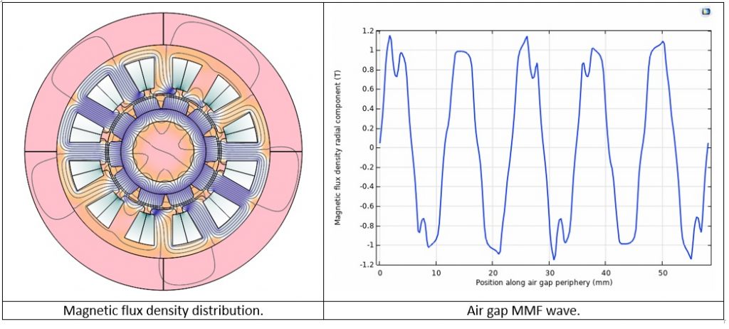
When it comes to designing electrical machines, the magnetic field distribution along the air gap periphery is a very crucial factor. It is also referred to as the air gap magneto-motive force (MMF) wave. It is basically the plot of the radial component of the magnetic field along the circumference of the air gap. The voltages induced in the stator coils directly depend on the shape of the MMF wave. If the wave has a sinusoidal shape, the stator phase will have a pure sinusoidal voltage, whereas if there is a nonsinusoidal MMF wave, higher-order harmonics will be present in the induced stator voltages. For a generator, the presence of harmonics will result in poor power quality supplied to the power system, while for a motor, any higher-order harmonics imply wasted power and therefore reduced efficiency.
From the COMSOL simulation of the PMM, we obtain the magnetic field distribution and the air gap MMF wave. Simply by inspecting the MMF wave in this case, we know that there will not be a purely sinusoidal voltage induced in the stator phase.
Investigating the Electromagnetic Torque
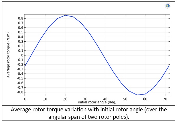
Let’s take a closer look at the model in terms of generating maximum electromagnetic torque. There are many approaches we can use for exciting stator windings in a PMM with a specific slot/pole configuration. The pattern in the motor’s schematic details one way that we can drive a 12-slot, 10-pole PM motor. By adjusting either the initial rotor position or phase of the stator coil excitation, we can apply the maximum torque to the rotor. We give the rotor an initial angular displacement and vary the angle over an angular span of a rotor magnet. We can then calculate the average torque value over the entire range. We choose the initial angular displacement corresponding to the maximum average torque as the rotor’s initial position. Therefore, it is easy to visualize the relative positions of the stator and rotor that produce the maximum torque. This study illustrates the use of parametric sweep in COMSOL Multiphysics® to vary the motor’s design parameters and analyze their effects on the motor performance with ease.
In the plot of the average torque curve, we can observe two maxima:
- The initial angular position corresponding to the positive maximum will result in counter-clockwise rotation (with proper stator coil excitation sequence)
- The initial angular position corresponding to the negative maximum will cause a clockwise rotation (with corresponding stator coil excitation sequence)
Assessing Iron Usage and Losses
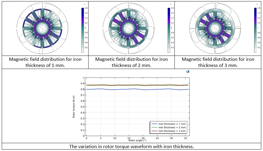
By observing a surface plot of magnetic flux density, we can gain a lot of insight into the performance of the machine. The color legend in the three magnetic field plots below indicate the magnetic flux density values. If we see a large difference of color in different portions of the yoke, it indicates that the yoke thickness may be reduced to even out the flux distribution in the yoke. This will result in better utilization of the iron for setting up the magnetic flux. If some portion of the yoke forms a bottleneck for the magnetic flux, it could cause the magnetic flux density value to move into the non-linear region of the hysteresis curve. Sometimes, a specific part of the yoke will consistently show a weak field, which implies that, for torque production, it is underutilized. If a consistent bottleneck forms at a certain part, we should probably widen it. If hotspots (tiny areas with large color difference compared to the surroundings) are observed in any region of the yoke, they indicate regions of a very high local magnetic flux density. Over time, these hotspots will cause local overheating, thermal expansion, and persistent localized mechanical stresses, which in turn will considerably reduce the functional life of the machine. These may be mitigated by widening the yoke or perhaps introducing rounds or fillets at sharp corners.
In this example, we vary the thicknesses of the rotor and stator iron and examine its influence on rotor torque. From the average torque curve shown in the previous section, the initial rotor angle of 20° corresponding to the positive maximum is chosen for this study. The graph given below shows the torque waveforms for different iron thickness values. The surface plots of the magnetic flux density for the three thickness values can be used to inspect the iron utilization and correlate them with the corresponding torque waveforms. It can be inferred from the plots that optimal iron utilization occurs when the iron thickness is 2 mm. When the thickness is less than 2 mm, torque reduces. If the thickness is more than 2 mm, the extra material adds unnecessary weight, and adds to the cost of the motor, while still generating the same torque value.
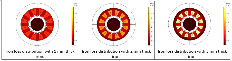
That is not the complete picture, though: While determining iron thickness, factors including mechanical strength and electromagnetic losses also play an important role. We can also evaluate the effect of varied iron thickness on iron losses, while analyzing the flux density and EM torque. COMSOL Multiphysics® has a Loss Calculation feature that can be used to easily compute copper losses and iron losses via:
- The Steinmetz equation
- The Bertotti formulation
- A loss model defined by the software user
Concluding Remarks
In this article, we have talked about gaining insight into some electric motor design aspects using the capabilities of COMSOL Multiphysics®. Probing the air gap MMF wave helps us gauge the impact on generator power quality or motor efficiency. We have seen how the motor torque can be maximized with respect to machine parameters using the Parametric Sweep feature in COMSOL Multiphysics®. A multipronged analysis of the motor by observing the magnetic field distribution, electromagnetic torque, and iron loss distribution allows us to squeeze the maximum performance for the same device size with minimal weight and material costs.
COMSOL Multiphysics is a registered trademark of COMSOL AB.
 |
Dr. Rahul Bhat, Applications Engineer, COMSOL. |